Monday, May 28, 2018

Spin-3/2 superconductor is a first, say physicists


Cooper pairs
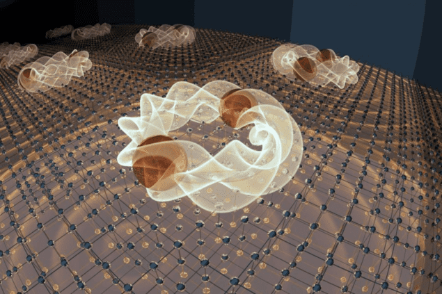
High spin: artist's impression of spin-3/2 Cooper pairs (Courtesy: Emily Edwards/University of Maryland)
The first known superconductor in which spin-3/2 quasiparticles form Cooper pairs has been created by physicists in the US and New Zealand. The unconventional superconductor is an alloy of yttrium, platinum and bismuth, which is normally a topological semimetal.
The research was done by Johnpierre Paglione and colleagues at the University of Maryland, Iowa State’s Ames Laboratory, the Lawrence Berkeley National Laboratory and the Universities of Otago and Wisconsin.
Conventional superconductivity arises in a material when spin-1/2 electrons form “Cooper pairs” because of interactions between the electrons and vibrations of the material’s crystalline lattice. These pairs are bosons with integer (usually zero) spin, which means that at very low temperatures they can condense to form a state that conducts electrical current with no resistance.

Spin-orbit interaction

In the alloy studied by Paglione and colleagues, charge is carried by particle-like quasiparticles with spin-3/2. These quasiparticles arise from interactions between the spins of electrons and the positive charges of the atoms that make up the alloy. This effect is called spin-orbit coupling and is particularly strong in this material. The result is that the spin-3/2 state – which combines spin and orbital angular momentum – is the lowest energy state.
http://www.viewray.com/linac-systemAdvertisement
When the team cooled the material, they found that it is a superconductor at temperatures below about 800 mK. This came as a surprise because this temperature is nearly 1000 times higher than expected if the superconductivity involved conventional Cooper pairs.
Paglione and colleagues also studied how magnetic fields penetrate the material. Superconductors can expel magnetic fields but the process is not perfect, with some magnetic field lines penetrating the surface of the material and persisting to small depths. Measuring this penetration effect gives important details about the nature of the pairing responsible for superconductivity.

Mind the gap

When the team measured the penetration depth as a function of temperature, they found that it increased linearly rather than exponentially – the latter being a characteristic of a conventional superconductor. This suggests that the energy gap between the superconducting and normal states of the material is not isotrophic in space, as is the case in conventional superconductors.
No one had really thought that this was possible in solid materials
Johnpierre Paglione, University of Maryland
This rules out spin-1/2 Cooper pairs so the team investigated other possibilities. They found that all possible pairings of spin-1/2 and spin-3/2 s in the alloy resulted in isotrophic gaps except the case where two spin-3/2 quasiparticles join to make a pair with a combined spin of 3.
“No one had really thought that this was possible in solid materials,” says Paglione, adding it “was quite a surprise given the simplicity of the electronic structure in this system”.

Non-trivial topology

What is particularly exciting about the material, say the researchers, is the topological nature of how the superconductivity arises. The spin-3/2 quasiparticles are a result of topology related to the strong spin-orbit coupling. Paglione also says, “the superconductivity that forms may itself have a non-trivial topology”. “This is a more subtle thing and harder to prove,” he adds, “but essentially the phase of the superconducting wave function may have a ‘twist’ in it that gives a non-trivial (chiral) topology. This has profound implications, such as possibility of Majorana fermion excitations from the superconducting condensate.”        Indeed, an important fundamental question, says Paglione, is how the spin-3/2 fermions pair up in the first place. “What’s the glue that holds these pairs together?” he asks. “There are some ideas of what might be happening, but fundamental questions remain – which makes it even more fascinating.”Paglione says that spin-3/2 superconductivity could exist in other materials and the phenomenon could have technological and fundamental applications. If such superconductors are indeed topological, he believes that they could form the basis for fault-tolerant quantum computers. On a fundamental level, he says that spin-3/2 fermions provide a very rich spectrum of possible pairing configurations for physicists to study – adding that their work has already garnered significant interest from other physicists.
The research is described in Science Advances.

Stephen Hawking’s last paper predicts a smooth exit from eternal inflation


Illustration of the expansion of the universe
Just the one: illustration of the expansion of the universe
What was Stephen Hawking working on just before his death last week?
While I’m sure he had several irons in the fire, he had just put the finishing touches on a paper about inflation and the multiverse – which he co-authored with Thomas Hertog of the University of Leuven in Belgian.The paper presents preliminary calculations that combine quantum and classical physics. The research explores whether an “infinite fractal-like multiverse” was created by the cosmic inflation that occurred just after the Big Bang. Hawking and Hertog’s calculations seem to say no.“A smooth exit from eternal inflation?” was uploaded to the arXiv preprint server in July 2017 and was updated on 4 March, just 10 days before Hawking’s death. According to reports in several media outlets, the paper has been submitted to a journal for peer review.

China launches ‘Queqiao’ lunar satellite


Artist's impression of the Queqiao lunar craft
Flying high: The Queqiao satellite will communicate between Earth and a lander that will be places on the far side of the Moon later this year (Courtesy: China Aerospace Science and Technology Corporation)

China has successfully launched a satellite to the Moon that will perform radio astronomy as well as communicate between Earth and a separate lunar lander, which is set for launch later this this year. Dubbed Queqiao, or Magpie Bridge from an ancient Chinese folklore tale, it took-off from the Xichang Satellite Launch Center on 21 May. It will now be put at Langrange Point 2 “L2” – a gravitational-balance point about 65000 km behind the Moon – where it will stay visible both to ground stations on Earth and the future lander.
Due to tidal locking between the Earth and the Moon, only one side of the Moon is visible to Earth. This “far side” remains of enormous interest to scientists as studies have indicated that there is a very different world on the far side, being geologically more ancient and dominated by highlands, unlike the planar landscape that prevails on the near side.
"A radio antenna behind the moon will open up a new window on the universe"  Marc Klein Wolt
The far side is also of interest for the radio-astronomy community. While almost all celestial radio wave frequencies can be received on Earth, those that are below 30 MHz are blocked by the atmosphere. Yet such frequencies contain important information about the early universe and can only be measured from a special vantage point like the back of the moon, which is free from atmospheric and man-made interference. This means the far side is one of the best places to measure the 21 cm hydrogen emission line that can be used to study the mass and dynamics of galaxies and will allow scientists to peer into the “cosmological dark ages” – a period between the Big Bang and the birth of the first stars.
Queqiao will include a Dutch-built antenna – the Netherlands-China Low-Frequency Explorer (NCLE) – that is designed to measure radio waves between 1-80 MHz. “A radio antenna behind the moon will open up a new window on the universe,” says NCLE project leader Marc Klein Wolt, who is managing director of the Radboud Radio Lab at Radboud University. According to Albert-Jan Boonstra from the Netherlands Institute for Radio Astronomy in Dwingeloo, the Dutch antenna is especially designed to receive low-frequency radio waves over a larger range. “We have found ways to avoid the electromagnetic interference of the satellite itself and successfully developed a broadband receiver,” he says.
Limited observations 
Also riding on Queqiao is a pair of microsatellites that will be released into an elliptical lunar orbit for similar radio astronomy experiments as the Dutch antenna. The twin microsatellites, developed by Chinese scientists, will carry out interferometry tests to demonstrate the feasibility of a future microsatellite array, which would be more sensitive than a single probe in detecting faint-radio signals from afar. However, due to the size of the microsatellites, their observation times will be limited to 10 minutes from the far side and 20 minutes of data transmission from the near side every orbit.                                                                                                                                                         As well as performing radio astronomy, another key aim of the Queqiao mission is to enable the transmission of commands and data from Earth to the Chang’e-4 lander that will launch later this year. Chang’e-4, which will land in the South Pole-Aitken Basin area, will be the first mission to the land on the far side of the Moon and it will also have a low-frequency radio-spectrum analyzer, which has been developed by scientists from the Institute of Electronics, Chinese Academy of Science in Beijing.

Skyrmions have attractive and repulsive tendencies

Skyrmions have attractive and repulsive tendencies


Skyrmions
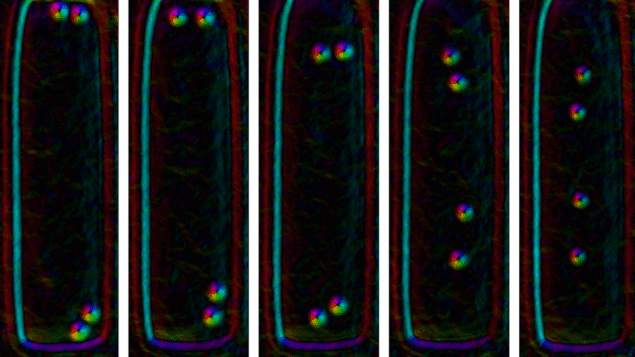
On the move: a sequence of electron micrographs showing pairs of skyrmions as they respond to a magnetic field that increases from left to right. (Courtesy: Haifeng Du et al/Phys. Rev. Lett.)

Interactions between individual 3D skyrmions have been measured by physicists in China, Sweden, Russia and Germany. Their study shows that the magnetic quasiparticles feel both attractive and repulsive forces, depending on the strength of an applied magnetic field. As well as providing insights into the fundamental physics of magnetic materials, the research could lead to the development of devices that store data using skyrmions.
Skyrmions were first proposed as a new type of fundamental particle in the 1950s by British physicist Tony Skyrme. While these hypothetical particles have never been seen, certain collective particle-like excitations (quasiparticles) in magnetic solids have been shown to behave much like skyrmions. These solid-state skyrmions resemble vortices and have topological stability, which means that they persist for very long times and are resilient to external perturbations such as noise. Skyrmions can be extremely small and be manipulated using relatively small amounts of energy. Together, these properties suggest that skyrmions could be used to make dense and energy efficient computer memories.
In this latest work, Mingliang Tian at the University of Science and Technology of China and colleagues studied a type of skyrmion that is created when a magnetic field is applied to a “nanostripe” of iron germanide (FeGe). These 3D skyrmions are tubular magnetic vortices with diameters of about 40 nm. They extend below the surface of the nanostripe and can move around in directions perpendicular to the applied magnetic field.

Edge effects

Using Lorentz transmission electron microscopy, the team observed the motions of individual skyrmions and then worked-out how the skyrmions interact with each other. They also studied how the skyrmions interact with the edges of the nanostripe, which was about 430 nm wide, 120 nm thick and 1600 nm long.
The team first looked at a nanostripe that contained tens of skyrmions. At relatively low magnetic fields (260 mT), the skyrmions formed chains or clusters at or near the edges of the nanostripe. As the field strength was increased to 390 mT, the clusters and chains moved away from the edges to the centre of the nanostripe – where the cluster and chain configurations were maintained. When the field was turned up to 480 mT the clusters and chains broke apart and the skyrmions were distributed across the centre of nanostripe.
Writing in Physical Review Letters, Tian and colleages surmise that the chain and cluster formation at low magnetic fields is the result of an attractive interaction between skyrmions. The migration of the skyrmions away from the edges and the subsequent break-up of the chains and clusters suggests that both the skyrmion-skyrmion and skyrmion-edge interactions become repulsive at higher magnetic fields.

Pair potential

However, the team points out that clustering can also occur in systems of particles with repulsive interactions and so to get a better understanding of the interaction they looked at the behaviour of individual pairs of skyrmions.
http://www.viewray.com/linac-systemAdvertisement
Their second experiment began at low magnetic field and with two pairs of skyrmions – one pair at each end of the FeGe nanostripe (see figure). As the magnetic field was increased from 200 mT to 500 mT, the team measured the distance between the two skyrmions in a pair. They also measured the distances between individual skyrmions and the edge of the nanostripe.
The initial separation between skyrmions in a pair was about 75 nm and this increased very slowly until the magnetic field reached about 450 mT. Then, the separation jumped to about 200 nm where it saturated by the time the magnetic field reached 470 mT. The distance between a skyrmion and the edge of the nanostripe was about 50 nm at low fields and increased to 200 nm and saturated there at about 420 mT.
Similar behaviour was seen in reverse as the magnetic field was reduced back down to 200 mT. This, the team says, shows that the observed interactions are real – rather than the result of skyrmions being pinned by defects in the FeGe nanostripe.

Theoretical agreement

The experiments reveal that the skyrmion-edge interaction switches from attractive to repulsive at a significantly lower field than the switch that occurs in skyrmion-skyrmion interaction. The team also did theoretical calculations, which suggest that the observed behaviour can be explained using our current understanding of 3D skyrmions.
The research could lead to a better understanding of the possible density at which skyrmions could be packed together in a memory device, and how data could be stored and retrieved from such devices.
In the audio interview below, Mohit Randeria of the Ohio State University tells Hamish Johnston why physicists are interested in skyrmions.

Saturday, May 26, 2018

Neutrons fly left or right depending on size of colliding nuclei


Photograph of the PHENIX detector at RHIC
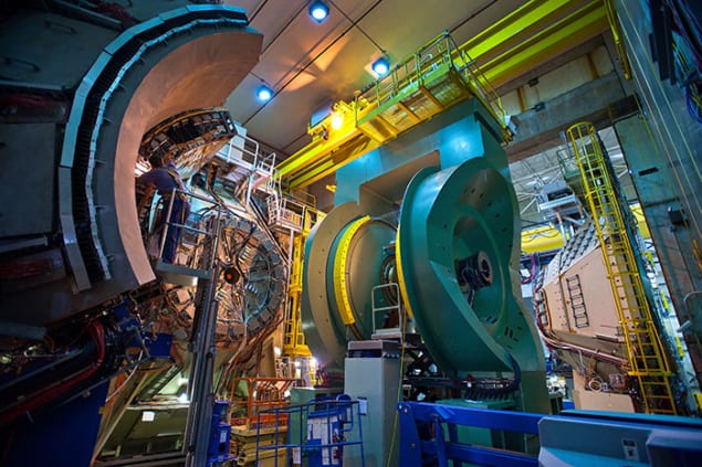
Right or left: the PHENIX detector at RHIC

Researchers at the Relativistic Heavy Ion Collider (RHIC) at Brookhaven National Lab (BNL) in the US have discovered that when spinning protons collide with nuclei they produce neutrons that fly-off in different directions that depend on the size of the target nucleus. The physicists say that this unexpected observation suggests that the neutrons-producing mechanism is different for large and small nuclei. They add that this could have important implications for interpreting other high-energy particle collisions, including the interactions of ultra-high-energy cosmic rays with the Earth’s atmosphere.
RHIC has been operating since 2000 and is the only collider in the world with the ability to precisely control the spin polarization of colliding protons. During its first polarized proton run in 2001–2002 researchers discovered that when a proton with upward spin collides with another proton, the neutron produced in the collision prefers to emerge to the right.
Almost a decade later, in 2011, theoretical physicists published a paper explaining this result. But then in 2015 a PhD student at Seoul National University in South Korea and BNL, Minjung Kim, made a surprise discovery. She observed that when protons collided with gold nuclei – which are much larger than protons – they produce a neutron with a strong preference to travel in the other direction: to the left.

Completely unexpected

This change in directional preference was not predicted by the 2011 theory. “What we found from the collisions with gold nuclei in 2015 was not only that the asymmetry magnitude increased by a factor of around three, but also its sign flipped, with the preferred scattering direction changing from the right to the left,” Alexander Bazilevsky, a physicist at BNL and deputy spokesperson for the PHENIXcollaboration at RHIC, tells Physics World. “It was completely unexpected.”
To confirm Kim’s finding, PHENIX physicists worked on data analysis and detector simulations, and repeated the measurements under more precisely controlled conditions. These new experiments also included collisions between protons and aluminium nuclei, which sit between protons and gold nuclei in size.
The results confirmed that proton-proton collisions produce a directional asymmetry with more neutrons scattering to the right, while proton-gold collisions produce a stronger asymmetry with neutrons scattering to the left. And, collisions with the intermediate-sized aluminium ions produced neutrons with near zero asymmetry – a roughly equal number scattered in each direction.

Charged collisions

To explain their findings the physicists looked closely at the processes and forces affecting the scattering particles. They concluded that in proton–proton collisions the asymmetry is driven by interactions governed by the strong nuclear force, as described in the 2011 theory. In large nuclei with more positive electric charge, however, electromagnetic interactions play a much more important role in particle production than in collisions between two equally charged protons.           Advertisement.
“We believe due to much larger electric charge of gold nucleus compared to proton, the electromagnetic interactions take on a larger role for neutron production in competition with strong nuclear interactions, with generated asymmetry of opposite sign to the one produced by strong nuclear interactions,” explains Bazilevsky. He adds that in medium sized aluminium nuclei the asymmetries generated by nuclear and electromagnetic interactions cancel each other out, and the result is no directional asymmetry in the resulting neutrons. “As our paper shows, the asymmetry sign flip happens around the aluminium nucleus, hence we would expect all nucleus lighter than aluminium would generate negative asymmetry (right preference), and all heavier nucleus would produce positive asymmetry (left preference),” he explains.                                                                          Via - PHYSICS WORLD

Iron in Earth’s core might be cubic, not hexagonal


Earth core
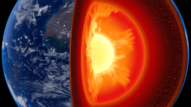
Cubic core: what is the crystal structure of iron at the centre of the Earth? (Courtesy: shutterstock/Johan Swanepoel)
A long-standing debate about the structure of solid iron at the centre of the Earth looks set to be reignited following new laboratory tests carried out by scientists in the US. The researchers say their results imply that iron crystals in the Earth’s inner core have a body-centred cubic (BCC) arrangement – in contrast to the hexagonal-close-packed (HCP) structure pointed to by many previous results.
Scientists have good evidence that the exceptionally high pressures that exist in Earth’s inner core dictate that the iron there is solid – in contrast to the molten iron present in the outer core. That evidence comes in the form of data from earthquakes. By plotting the paths of seismic waves through the Earth, seismologists have concluded that shear waves – which cannot propagate in liquids – do not travel through the outer core but do travel through the inner one.
However, for several decades debate has raged about how the atoms in that solid iron are arranged. At room temperature and pressure, iron has a bcc lattice, which means that every atom is surrounded by eight others – four in each of the layers immediately above and below it. But at higher pressures, iron atoms form the slightly tighter hcp structure, such that each atom has 12 neighbours – six in its own layer and three in those above and below it.

Diamond anvils

The situation at very high temperatures and pressures, however, is not well understood. Several experiments using iron heated inside high-pressure diamond anvil cells have shown that here too the structure is hcp. These experiments involve squeezing tiny samples of iron between the tips of diamonds, heating them with a laser beam and at the same time illuminating them with X-rays from a synchrotron source to determine the crystal structure from the X-ray diffraction pattern.
In fact, according to Guoyin Shen of the Carnegie Institution of Washington, most Earth scientists are persuaded that the iron in the inner core does in fact have a hexagonal-shaped lattice. “Within the community,” he says, “many think that it is a done deal – that the structure of iron seems to be hcp.”

Seismic anisotropy

There is a problem, however. Seismologists have established that shock waves from earthquakes travel more quickly through the Earth when they go from pole to pole than when they go along the equator. This “anisotropy” ought to be reflected in the structure of the iron, such that it is significantly more elastic at right angles to its atomic layers than it is parallel to them. In other words, that the spacing, and hence the give, between adjacent layers should be significantly greater than that between neighbouring atoms within the same layer. But theorists have calculated that very high temperatures should flatten hcp iron – making the difference in spacing too small to account for the seismic anisotropy.
http://www.viewray.com/linac-systemAdvertisement
In the latest research, Shen and his Carnegie colleagues Ross Hrubiak and Yue Meng show experimentally that the inner core iron might in fact have a bcc structure. They did so after realizing that the diamond cell experiments could be giving misleading results. These “in-situ” measurements provide X-ray diffraction patterns of the iron during the brief period that it is heated by the laser. But because the X-ray beam is not much narrower than the hot spot created by the laser there is a chance, says Shen, that the high-temperature data become “contaminated” by data from regions at lower temperatures.
To try and get round this problem, Shen and co-workers have developed an alternative technique in which they compress samples of iron in a diamond anvil cell but this time take X-ray diffraction images before, during and after each heating pulse. Using the HPCAT beamline at the Argonne National Laboratory’s Advanced Photon Source, they find that at relatively low pressures and temperatures the diffraction patterns are as would be expected from hcp-iron grains.

Two distinct axes

However, once the group raised the pressure above about 10atm and the temperature well above 4000 K it discovered that the crystal grains became oriented along two distinct axes. Because the grains’ orientation might be preserved across phase transitions, the researchers say that this “bi-axially aligned microstructure” is evidence that the iron adopts a bcc structure at high temperatures and then transforms back into hcp when it cools down
Buoyed by these results, Shen and colleagues then carried out fresh measurements at inner-core like conditions. They realized that, as they and other groups had found previously, many of the spots in the diffraction pattern would be due to hcp-iron. But they predicted that they should also see one spot due to bcc-iron in a particular orientation – and say that they have observed it. “In earlier experiments we considered that diffraction spot as noise,” says Shen, “but now it becomes evidence that supports our view.”
Shen acknowledges that others in the field are likely to be sceptical, given potential doubts about his group’s interpretation of the microstructure data and the fact that it has so far only seen one family of diffraction planes that it can attribute to bcc-iron. He says that he and his colleagues are now focused on trying to improve the in-situ measurements, either by reducing the X-ray spot size or increasing the X-ray energy to boost chances of finding more diffraction information.                                                                                              Via - Physics World

Landauer principle passes quantum muster

Landauer principle passes quantum muster

Landauer principle
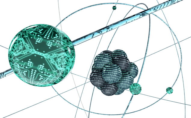
Principled ion: a minimum amount of energy is required to erase a quantum bit. (Courtesy: iStock/thelightwriter)
The minimum amount energy needed to erase a quantum bit (qubit) of information has been measured for the first time. Using a trapped ion as a qubit, Mang Feng of the Chinese Academy of Sciences in Wuhan and colleagues have confirmed that “Landauer’s principle” applies to quantum information as well as classical information.
http://www.viewray.com/linac-systemAdvertisement
Devised in 1961 by the German–American physicist Rolf Landauer, the principle says that the irreversible erasure of information involves the dissipation of heat. This confirmation in the quantum realm could lead to the development of practical erasure systems for quantum computers.
One important example of Landauer’s principle is the “reset-to-one” process, whereby a bit of information, which can be either 0 or 1, is reset to 1. As the bit can no longer have one of two possible values, its entropy – or randomness – is reduced. And given that the bit and its surroundings are physical entities that must obey the laws of thermodynamics, the entropy must therefore be transferred from the bit to its surroundings as heat.

Tiny amount of heat

Landauer’s principle says that a minimum amount of heat – about 10-21 J per erased bit – must be dissipated when information is destroyed. This is a tiny amount of energy and it was not until 2012 that physicists in Germany and France were able to confirm the principle, using a tiny silica bead trapped in optical tweezers as an unlikely datum bit.
While a classical bit can be either 0 or 1, a qubit can be in a combination of both states at the same time. However, Landauer’s principle should also apply, predicting a similar minimum amount of heat dissipated.
Now, Feng and colleagues have verified this notion by storing and then erasing information held in a single ion of calcium-40 that is trapped at ultracold temperatures using magnetic fields. Information was stored in terms of whether the ion is in one of two internal quantum states dubbed 0 and 1. The ion can vibrate within the trap and can therefore exchange heat energy with its surroundings via transitions between its quantized vibrational modes.

Maximally mixed

Using a series of laser pulses, the ion qubit was first put into a quantum state in which the 0 and 1 states are equally populated. This is a state of maximal entropy called a “maximally mixed state”. A laser pulse then couples the internal states of the ion to its vibrational motion, which allows the ion togive up energy to its surroundings. This process results in the partial erasure of the quantum information as well as the conversion of entropy into heat.
By repeating the process many times while monitoring the internal quantum state and vibrational modes of the ion, Feng and colleagues were able to confirm that Landauer’s principle applies in the quantum regime.
Writing in Physical Review Letters, the team describes its work as “an imperative step towards better understanding of the fundamental physical limitations of irreversible logic operations at the quantum level”. The researchers also hope that their work will aid in the design of an “artificial quantum reservoir” that would initialize quantum computers of the future by rapidly removing encoded information from large numbers of qubits. They caution, however, that the development of a practical erasure system will be a challenge because quantum erasure requires more heat to do than in classical systems – because of correlations between the qubit and the heat reservoir.                                                                 via Physics World

Friday, May 25, 2018

Time Travel Is 'Technically Possible' Says Physicist - But You'll ONLY Be Able To Go Backwards


As the common tropes of our science fiction continue to break out into reality every now and then, from humanoid robots to self-driving cars, there’s one concept that has seemingly remained beyond our grasp: time travel. But, jumping through time might not be impossible, after all, according to one astrophysicist.

By the rules of theoretical physics, certain conditions exist that would allow for the construction of elaborate wormholes, which could transport humans back to different eras.While scientists have yet to discover the conditions needed to travel back in time, and construction a system large enough for humans certainly wouldn’t be easy, ‘there’s nothing forbidding it’ in the laws of theoretical physics, explains astrophysicist Ethan Siegel of Lewis & Clark College in the Forbes blog Starts With A Bang.
Backward time travel would rely on the elusive counterpart to the known positive energy / positive or zero mass particles found all throughout the universe – the negative mass/energy particles, which have long been theorized but never yet found.

‘If this negative mass/energy matter exists, then creating both a supermassive black hole and the negative mass/energy counterpart to it, while then connecting them, should allow for a traversable wormhole,’ Siegel writes.
‘No matter how far apart you took these to connected objects from one another, if they had enough mass/energy – of both the positive and the negative kind – this instantaneous connection would remain.’The wormhole could be constructed in a way that allows one end to remain nearly motionless, while the other moves at almost the speed of light. Entering such a tunnel could then, theoretically, allow a person to jump back through time.Siegel imagines a scenario in which the destination is 40 light years away. After the passage of one year, the fast-moving end of the wormhole would have aged 40 years, while only a year would have passed on the other side. ‘If, 40 years ago, someone had created such a pair of entangled wormholes and sent them off on this journey, it would be possible to step into one of them today, in 2017, and wind up back in time at the mouth of the other one... back in 1978,’ Siegel writes.

‘The only issue is that you yourself couldn't also have been at that location back in 1978; you needed to be with the other end of the wormhole, or traveling through space to try and catch up with it.’
Via Daily Mail

Three-phase Electricity...


Three-phase electric power is a common method of alternating current electric powergenerationtransmission, and distribution. It is a type of polyphase system and is the most common method used by electrical gridsworldwide to transfer power. It is also used to power large motors and other heavy loads.
Three-phase transformer with four wire output for 208Y/120 volt service: one wire for neutral, others for A, B and C phases

A three-wire three-phase circuit is usually more economical than an equivalent two-wire single-phase circuit at the same line to ground voltage because it uses less conductor material to transmit a given amount of electrical power. Polyphase power systems were independently invented by Galileo FerrarisMikhail Dolivo-DobrovolskyJonas WenströmJohn Hopkinson and Nikola Teslain the late 1880s.

Principle


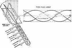
Normalized waveforms of the instantaneous voltages in a three-phase system in one cycle with time increasing to the right. The phase order is 1‑2‑3. This cycle repeats with the frequency of the power system. Ideally, each phase’s voltage, current, and power is offset from the others’ by 120°.
Three-phase electric power transmission lines
Three-phase transformer (Békéscsaba, Hungary): on the left are the primary wires and on the right are the secondary wires

In a symmetric three-phase power supply system, three conductors each carry an alternating current of the same frequency and voltage amplitude relative to a common reference but with a phase difference of one third of a cycle between each. The common reference is usually connected to ground and often to a current-carrying conductor called the neutral. Due to the phase difference, the voltage on any conductor reaches its peak at one third of a cycle after one of the other conductors and one third of a cycle before the remaining conductor. This phase delay gives constant power transfer to a balanced linear load. It also makes it possible to produce a rotating magnetic field in an electric motorand generate other phase arrangements using transformers (for instance, a two phase system using a Scott-T transformer).
The symmetric three-phase systems described here are simply referred to as three-phase systems because, although it is possible to design and implement asymmetric three-phase power systems (i.e., with unequal voltages or phase shifts), they are not used in practice because they lack the most important advantages of symmetric systems.
In a three-phase system feeding a balanced and linear load, the sum of the instantaneous currents of the three conductors is zero. In other words, the current in each conductor is equal in magnitude to the sum of the currents in the other two, but with the opposite sign. The return path for the current in any phase conductor is the other two phase conductors.

Advantages

As compared to a single-phase AC power supply that uses two conductors (phase and neutral), a three-phase supply with no neutral and the same phase-to-ground voltage and current capacity per phase can transmit three times as much power using just 1.5 times as many wires (i.e., three instead of two). Thus, the ratio of capacity to conductor material is doubled. The ratio of capacity to conductor material increases to 3:1 with an ungrounded three-phase and center-grounded single-phase system (or 2.25:1 if both employ grounds of the same gauge as the conductors).
Constant power transfer and cancelling phase currents would in theory be possible with any number (greater than one) of phases, maintaining the capacity-to-conductor material ratio that is twice that of single-phase power. However, two-phase power results in a less smooth (pulsating) torque in a generator or motor (making smooth power transfer a challenge), and more than three phases complicates infrastructure unnecessarily.
Three-phase systems may also have a fourth wire, particularly in low-voltage distribution. This is the neutral wire. The neutral allows three separate single-phase supplies to be provided at a constant voltage and is commonly used for supplying groups of domestic properties which are each single-phase loads. The connections are arranged so that, as far as possible in each group, equal power is drawn from each phase. Further up the distribution system, the currents are usually well balanced. Transformers may be wired in a way that they have a four-wire secondary but a three-wire primary while allowing unbalanced loads and the associated secondary-side neutral currents.
Three-phase supplies have properties that make them very desirable in electric power distribution systems:
  • The phase currents tend to cancel out one another, summing to zero in the case of a linear balanced load. This makes it possible to reduce the size of the neutral conductor because it carries little or no current. With a balanced load, all the phase conductors carry the same current and so can be the same size.
  • Power transfer into a linear balanced load is constant, which helps to reduce generator and motor vibrations.
  • Three-phase systems can produce a rotating magnetic field with a specified direction and constant magnitude, which simplifies the design of electric motors, as no starting circuit is required.
Most household loads are single-phase. In North American residences, three-phase power might feed a multiple-unit apartment block, but the household loads are connected only as single phase. In lower-density areas, only a single phase might be used for distribution. Some high-power domestic appliances such as electric stoves and clothes dryers are powered by a split phase system at 240 volts or from two phases of a three phase system at 208 volts.

Phase sequence

Wiring for the three phases is typically identified by color codes which vary by country. Connection of the phases in the right order is required to ensure the intended direction of rotation of three-phase motors. For example, pumps and fans may not work in reverse. Maintaining the identity of phases is required if there is any possibility two sources can be connected at the same time; a direct interconnection between two different phases is a short-circuit.

Generation and distribution


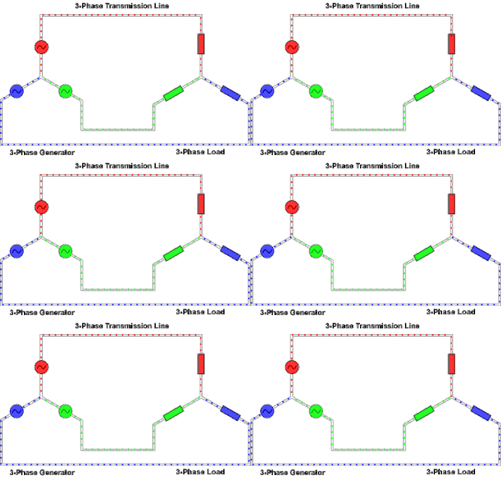
Animation of three-phase current

Left image: elementary six-wire three-phase alternator with each phase using a separate pair of transmission wires. Right image: elementary three-wire three-phase alternator showing how the phases can share only three wires.
At the power station, an electrical generatorconverts mechanical power into a set of three AC electric currents, one from each coil (or winding) of the generator. The windings are arranged such that the currents vary sinusoidally at the same frequency but with the peaks and troughs of their wave forms offset to provide three complementary currents with a phase separation of one-third cycle (120° or 3 radians). The generator frequency is typically 50 or 60 Hz, depending on the country.


Alternating current in a transformer. Voltage is induced in the secondary (right coil) only when the voltage is changing in the primary (left). This happens via electromagnetic induction.

At the power station, transformers change the voltage from generators to a level suitable for transmission in order to minimize losses.
After further voltage conversions in the transmission network, the voltage is finally transformed to the standard utilization before power is supplied to customers.
Most automotive alternators generate three-phase AC and rectify it to DC with a diode bridge.

Transformer connections

A "delta" connected transformer winding is connected between phases of a three-phase system. A "wye" transformer connects each winding from a phase wire to a common neutral point.
A single three-phase transformer can be used, or three single-phase transformers.
In an "open delta" or "V" system, only two transformers are used. A closed delta made of three single-phase transformers can operate as an open delta if one of the transformers has failed or needs to be removed. In open delta, each transformer must carry current for its respective phases as well as current for the third phase, therefore capacity is reduced to 87%. With one of three transformers missing and the remaining two at 87% efficiency, the capacity is 58% (23 of 87%).
Where a delta-fed system must be grounded for detection of stray current to ground or protection from surge voltages, a grounding transformer (usually a zigzag transformer) may be connected to allow ground fault currents to return from any phase to ground. Another variation is a "corner grounded" delta system, which is a closed delta that is grounded at one of the junctions of transformers.

Three-wire and four-wire circuits


Wye (Y) and delta (Δ) circuits

There are two basic three-phase configurations: wye (Y) and delta (Δ). As shown in the diagram, a delta configuration requires only three wires for transmission but a wye (star) configuration may have a fourth wire. The fourth wire, if present, is provided as a neutral and is normally grounded. The "3-wire" and "4-wire" designations do not count the ground wire present above many transmission lines, which is solely for fault protection and does not carry current under normal use.
A four-wire system with symmetrical voltages between phase and neutral is obtained when the neutral is connected to the "common star point" of all supply windings. In such a system, all three phases will have the same magnitude of voltage relative to the neutral. Other non-symmetrical systems have been used.
The four-wire wye system is used when a mixture of single-phase and three-phase loads are to be served, such as mixed lighting and motor loads. An example of application is local distribution in Europe (and elsewhere), where each customer may be only fed from one phase and the neutral (which is common to the three phases). When a group of customers sharing the neutral draw unequal phase currents, the common neutral wire carries the currents resulting from these imbalances. Electrical engineers try to design the three-phase power system for any one location so that the power drawn from each of three phases is the same, as far as possible at that site. Electrical engineers also try to arrange the distribution network so the loads are balanced as much as possible, since the same principles that apply to individual premises also apply to the wide-scale distribution system power. Hence, every effort is made by supply authorities to distribute the power drawn on each of the three phases over a large number of premises so that, on average, as nearly as possible a balanced load is seen at the point of supply.


A delta-wye configuration across a transformer core (note that a practical transformer would have a different number of coils on each side).

For domestic use, some countries such as the UK may supply one phase and neutral at a high current (up to 100 A) to one property, while others such as Germany may supply 3 phases and neutral to each customer, but at a lower fuse rating, typically 4063 A per phase, and "rotated" to avoid the effect that more load tends to be put on the first phase.[citation needed]


A transformer for a "high-leg delta" system used for mixed single-phase and three-phase loads on the same distribution system. Three-phase loads such as motors connect to L1, L2, and L3. Single-phase loads would be connected between L1 or L2 and neutral, or between L1 and L2. The L3 phase is 1.73 times the L1 or L2 voltage to neutral so this leg is not used for single-phase loads.

In North America, a high-leg delta supply is sometimes used where one winding of a delta-connected transformer feeding the load is center-tapped and that center tap is grounded and connected as a neutral as shown in the second diagram. This setup produces three different voltages: If the voltage between the center tap (neutral) and each of the top and bottom taps (phase and anti-phase) is 120 V (100%), the voltage across the phase and anti-phase lines is 240 V (200%), and the neutral to "high leg" voltage is ≈ 208 V (173%).
The reason for providing the delta connected supply is usually to power large motors requiring a rotating field. However, the premises concerned will also require the "normal" North American 120 V supplies, two of which are derived (180 degrees "out of phase") between the "neutral" and either of the center tapped phase points.

Balanced circuits

In the perfectly balanced case all three lines share equivalent loads. Examining the circuits we can derive relationships between line voltage and current, and load voltage and current for wye and delta connected loads.
In a balanced system each line will produce equal voltage magnitudes at phase angles equally spaced from each other. With V1 as our reference and V3 lagging V2 lagging V1, using angle notation, and VLN the voltage between the line and the neutral we have:
These voltages feed into either a wye or delta connected load.

Wye (Y) also called Star


Three-phase AC generator connected as a wye or star source to a wye or star connected load

The voltage seen by the load will depend on the load connection; for the wye case, connecting each load to a phase (line-to-neutral) voltages gives:
where Ztotal is the sum of line and load impedances (Ztotal = ZLN + ZY), and θ is the phase of the total impedance (Ztotal).
The phase angle difference between voltage and current of each phase is not necessarily 0 and is dependent on the type of load impedance, Zy. Inductive and capacitive loads will cause current to either lag or lead the voltage. However, the relative phase angle between each pair of lines (1 to 2, 2 to 3, and 3 to 1) will still be −120°.
By applying Kirchhoff's current law (KCL) to the neutral node, the three phase currents sum to the total current in the neutral line. In the balanced case:


A phasor diagram for a wye configuration, in which Vabrepresents a line voltage and Van represents a phase voltage. Voltages are balanced as:
Vab = (1∠α - 1∠α + 120°) 3*|V|∠α + 30°
Vbc = 3*|V|∠α - 90°
Vca = 3*|V|∠α + 150°
(α = 0 in this case)

Delta (Δ)


Three-phase AC generator connected as a wye source to a delta-connected load

In the delta circuit, loads are connected across the lines, and so loads see line-to-line voltages:
v1 is the phase shift for the first voltage, commonly taken to be 0° -- in this case Φv2 = -120° and Φv3 = -240° or 120°)
Further:
where θ is the phase of delta impedance (ZΔ).
Relative angles are preserved, so I31 lags I23lags I12 by 120°. Calculating line currents by using KCL at each delta node gives:
and similarly for each other line:
where, again, θ is the phase of delta impedance (ZΔ).


A delta configuration and a corresponding phasor diagram of its currents. Phase voltages are equal to line voltages, and currents are calculated as:
Ia = Iab - Ica = 3Iab∠-30°
Ib = Ibc - Iab
Ic = Ica - Ibc
The overall power transferred is
S = 3VphaseI*phase

Inspection of a phasor diagram, or conversion from phasor notation to complex notation, illuminates how the difference between two line-to-neutral voltages yields a line-to-line voltage that is greater by a factor of 3. As a delta configuration connects a load across phases of a transformer, it delivers the line-to-line voltage difference, which is 3 times greater than the line-to-neutral voltage delivered to a load in the wye configuration. As the power transferred is V2/Z, the impedance in the delta configuration must be 3 times what it would be in a wye configuration for the same power to be transferred.

Single-phase loads

Except in a high-leg delta system, single-phase loads may be connected across any two phases, or a load can be connected from phase to neutral. Distributing single-phase loads among the phases of a three-phase system balances the load and makes most economical use of conductors and transformers.
In a symmetrical three-phase four-wire, wye system, the three phase conductors have the same voltage to the system neutral. The voltage between line conductors is 3 times the phase conductor to neutral voltage:
The currents returning from the customers' premises to the supply transformer all share the neutral wire. If the loads are evenly distributed on all three phases, the sum of the returning currents in the neutral wire is approximately zero. Any unbalanced phase loading on the secondary side of the transformer will use the transformer capacity inefficiently.
If the supply neutral is broken, phase-to-neutral voltage is no longer maintained. Phases with higher relative loading will experience reduced voltage, and phases with lower relative loading will experience elevated voltage, up to the phase-to-phase voltage.
high-leg delta provides phase-to-neutral relationship of VLL = 2 VLN, however, LN load is imposed on one phase. A transformer manufacturer's page suggests that LN loading not exceed 5% of transformer capacity.
Since 3 ≈ 1.73, defining VLN as 100% gives VLL ≈ 100% × 1.73 = 173%. If VLL was set as 100%, then VLN ≈ 57.7%.

Unbalanced loads

When the currents on the three live wires of a three-phase system are not equal or are not at an exact 120° phase angle, the power loss is greater than for a perfectly balanced system. The method of symmetrical components is used to analyze unbalanced systems.

Non-linear loads

With linear loads, the neutral only carries the current due to imbalance between the phases. Gas-discharge lamps and devices that utilize rectifier-capacitor front-end such as switch-mode power supplies, computers, office equipment and such produce third-order harmonics that are in-phase on all the supply phases. Consequently, such harmonic currents add in the neutral in a wye system (or in the grounded (zigzag) transformer in a delta system), which can cause the neutral current to exceed the phase current.

Three-phase loads

An important class of three-phase load is the electric motor. A three-phase induction motor has a simple design, inherently high starting torque and high efficiency. Such motors are applied in industry for many applications. A three-phase motor is more compact and less costly than a single-phase motor of the same voltage class and rating, and single-phase AC motors above 10 HP (7.5 kW) are uncommon. Three-phase motors also vibrate less and hence last longer than single-phase motors of the same power used under the same conditions.[citation needed]
Resistance heating loads such as electric boilers or space heating may be connected to three-phase systems. Electric lighting may also be similarly connected.
Line frequency flicker in light is detrimental to high speed cameras used in sports event broadcasting for slow motion replays. It can be reduced by evenly spreading line frequency operated light sources across the three phases so that the illuminated area is lit from all three phases. This technique was applied successfully at the 2008 Beijing Olympics.
Rectifiers may use a three-phase source to produce a six-pulse DC output. The output of such rectifiers is much smoother than rectified single phase and, unlike single-phase, does not drop to zero between pulses. Such rectifiers may be used for battery charging, electrolysis processes such as aluminium production or for operation of DC motors. "Zig-zag" transformers may make the equivalent of six-phase full-wave rectification, twelve pulses per cycle, and this method is occasionally employed to reduce the cost of the filtering components, while improving the quality of the resulting DC.


Three phase plug commonly used on electric stoves in Europe

One example of a three-phase load is the electric arc furnace used in steelmaking and in refining of ores.
In many European countries electric stoves are usually designed for a three-phase feed. Individual heating units are often connected between phase and neutral to allow for connection to a single-phase circuit if three-phase is not available. Other usual three-phase loads in the domestic field are tankless water heating systems and storage heaters. Homes in Europe and the UK have standardized on a nominal 230 V between any phase and ground. (Existing supplies remain near 240 V in the UK, and 220 V on much of the continent.) Most groups of houses are fed from a three-phase street transformer so that individual premises with above-average demand can be fed with a second or third phase connection.

Phase converters

Phase converters are used when three-phase equipment needs to be operated on a single-phase power source. They are used when three-phase power is not available or cost is not justifiable. Such converters may also allow the frequency to be varied, allowing speed control. Some railway locomotives use a single-phase source to drive three-phase motors fed through an electronic drive.
rotary phase converter is a three-phase motor with special starting arrangements and power factor correction that produces balanced three-phase voltages. When properly designed, these rotary converters can allow satisfactory operation of a three-phase motor on a single-phase source. In such a device, the energy storage is performed by the inertia(flywheel effect) of the rotating components. An external flywheel is sometimes found on one or both ends of the shaft.
A three-phase generator can be driven by a single-phase motor. This motor-generator combination can provide a frequency changer function as well as phase conversion, but requires two machines with all their expenses and losses. The motor-generator method can also form an uninterruptible power supplywhen used in conjunction with a large flywheel and a battery-powered DC motor; such a combination will deliver nearly constant power compared to the temporary frequency drop experienced with a standby generator set gives until the standby generator kicks in.
Capacitors and autotransformers can be used to approximate a three-phase system in a static phase converter, but the voltage and phase angle of the additional phase may only be useful for certain loads.
Variable-frequency drives and digital phase converters use power electronic devices to synthesize a balanced three-phase supply from single-phase input power.

Alternatives to three-phase

  • Split-phase electric power is used when three-phase power is not available and allows double the normal utilization voltage to be supplied for high-power loads.
  • Two-phase electric power uses two AC voltages, with a 90-electrical-degree phase shift between them. Two-phase circuits may be wired with two pairs of conductors, or two wires may be combined, requiring only three wires for the circuit. Currents in the common conductor add to 1.4 times the current in the individual phases, so the common conductor must be larger. Two-phase and three-phase systems can be interconnected by a Scott-T transformer, invented by Charles F. Scott. Very early AC machines, notably the first generators at Niagara Falls, used a two-phase system, and some remnant two-phase distribution systems still exist, but three-phase systems have displaced the two-phase system for modern installations.
  • Monocyclic power was a name for an asymmetrical modified two-phase power system used by General Electric around 1897, championed by Charles Proteus Steinmetz and Elihu Thomson. This system was devised to avoid patent infringement. In this system, a generator was wound with a full-voltage single-phase winding intended for lighting loads and with a small fraction (usually 1/4 of the line voltage) winding that produced a voltage in quadrature with the main windings. The intention was to use this "power wire" additional winding to provide starting torque for induction motors, with the main winding providing power for lighting loads. After the expiration of the Westinghouse patents on symmetrical two-phase and three-phase power distribution systems, the monocyclic system fell out of use; it was difficult to analyze and did not last long enough for satisfactory energy metering to be developed.
  • High-phase-order systems for power transmission have been built and tested. Such transmission lines typically would use six or twelve phases. High-phase-order transmission lines allow transfer of slightly less than proportionately higher power through a given volume without the expense of a high-voltage direct current(HVDC) converter at each end of the line. However, they require correspondingly more pieces of equipment.

Color codes

Conductors of a three-phase system are usually identified by a color code, to allow for balanced loading and to assure the correct phase rotation for motors. Colors used may adhere to International Standard IEC 60446(now merged into IEC 60445), older standards or to no standard at all and may vary even within a single installation. For example, in the U.S. and Canada, different color codes are used for grounded (earthed) and ungrounded systems.